Dilution refrigerator ready
Plan room, lifting, service access and facility interfaces for one or more refrigerators, together with their control and support equipment.
SETEK / QUANTUM INFRASTRUCTURE CONCEPT
Quantum-support infrastructure must manage cryogenic interfaces, vibration sensitivity, EMI exposure, power continuity and environmental control around the chosen quantum hardware—not around a conventional server-room assumption.
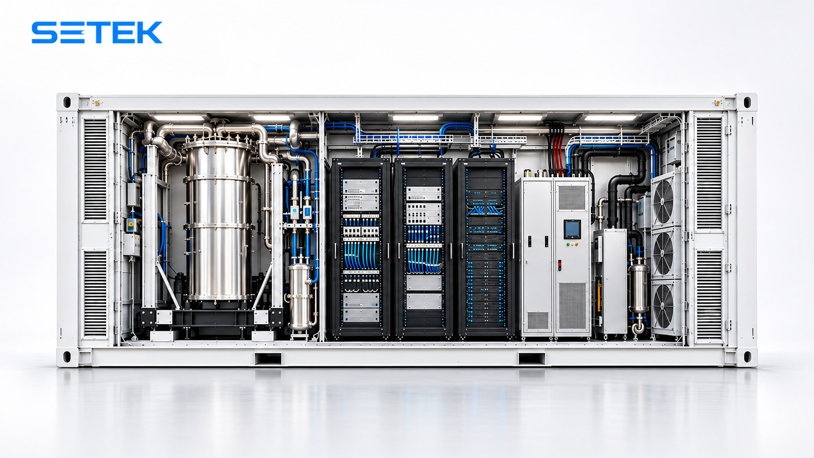
Illustrative product visualization. Compatibility and final configuration depend on the selected quantum OEM platform.
QUANTUM DATA CENTER
Quantum computers operate in a completely different regime from conventional IT. For superconducting platforms, the qubit device is stabilized at about 10–20 millikelvin inside a dilution refrigerator cryostat. The infrastructure outside the cryostat must reduce disturbances and provide the utilities that keep the quantum system operational.
Plan room, lifting, service access and facility interfaces for one or more refrigerators, together with their control and support equipment.
Anti-vibration floor concepts and isolation measures can be reviewed to reduce risks of qubit decoherence or instrument instability.
Faraday-cage or related shielding concepts are assessed against OEM-defined EMI and magnetic-field limits rather than assumed universally.
Quantum-support loads often require continuity for control electronics, utilities and safe shutdown sequences. UPS and generator strategies are evaluated per project.
Supporting rooms may require clean, stable environmental management for electronics, lasers, vacuum subsystems or operator areas.
Containerized layouts can support phased expansion as research equipment, cryogenic capacity or control hardware grows over time.
REFERENCE CONTAINER CONCEPTS
The following are concept-planning references derived from partner page information and reformulated for SETEK’s website. They are not final product commitments and always require OEM-specific design validation.
TECHNOLOGY FAMILIES
Different quantum-computing technologies need different cooling temperatures, optical interfaces and shielding responses. SETEK therefore starts from the hardware vendor’s requirements rather than from a fixed enclosure template.
| Technology family | Typical infrastructure priorities | Examples of design checks |
|---|---|---|
| Superconducting | Dilution refrigerator, microwave wiring, magnetic review, vibration control and facility cooling | Cryostat envelope, utility demand, service clearances, EMI / magnetic criteria |
| Trapped-ion | Vacuum systems, laser equipment, optical stability and precision environmental control | Optical path protection, vibration sensitivity, heat loads and room arrangement |
| Photonic | Optical modules, lasers, detectors and alignment-sensitive control electronics | Detector cooling needs, cable routing, optical layout and supporting utilities |
FAQ
Quantum hardware may operate near absolute zero inside its cryogenic system and can be highly sensitive to micro-vibration, electromagnetic interference and magnetic fields. That leads to very different infrastructure priorities than a standard server room.
A modular enclosure can accelerate deployment without requiring an entirely new building, support outdoor placement near existing research facilities and allow phased expansion as the program scales.
It is a cryogenic system that uses a helium-3 / helium-4 mixture to cool down to roughly 10–20 mK. That ultra-cold environment is essential for many superconducting qubit systems to maintain their quantum state.
The infrastructure concept can be adapted around superconducting, trapped-ion, photonic and other architectures, provided the equipment vendor’s requirements for cooling, shielding, vibration and utilities are defined clearly enough for engineering.
Important technical note: “~15 mK” refers to the qubit environment inside the dilution refrigerator cryostat, not to the air temperature of the whole container. Final compatibility, EMI/EMC compliance, shielding effectiveness, uptime strategy and environmental criteria must be confirmed through project-specific engineering and OEM data.
YOUR REQUIREMENTS, OUR STARTING POINT
Share your intended quantum platform, required utilities, site conditions and resilience targets. SETEK will coordinate the next engineering steps and scope.
Send a project enquiry ↗