Model 20
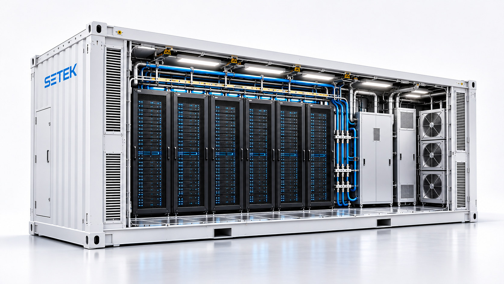
20-foot platform considered for edge AI, pilots or limited-footprint installations. Rack quantity, IT power and cooling approach are defined through project engineering.
Ideal when space and site interfaces are the primary constraints.
SETEK / AI PREFABRICATED MODULAR DATA CENTER
High-density computing works only when rack layout, protected power, liquid cooling, networking and operational monitoring are designed together. SETEK AI PMDC brings these interfaces into one factory-integrated concept, configured around each project.
MODEL OPTIONS
Model 20 and Model 40 are project configuration families, not fixed turnkey specifications. The usable load depends on the servers, rack arrangement, cooling infrastructure and service clearances.
20-foot platform considered for edge AI, pilots or limited-footprint installations. Rack quantity, IT power and cooling approach are defined through project engineering.
40-foot high-cube IT-module planning baseline with 10 rack positions for D2C-oriented concepts, coordinated with separate Power and Cooling Modules where needed.
THREE MODULES · ONE COORDINATED DESIGN
Separating compute, protected electrical power and thermal plant can create more usable IT space and clearer maintenance boundaries—but only with correctly engineered interconnections.
GPU servers, racks, internal network fabric, liquid manifolds, residual air, cable paths and service access.
Utility input, UPS, energy storage strategy, protective distribution, rack PDUs and metering.
CDUs, pumps, heat exchangers and external heat rejection matched to the IT loop and ambient conditions.
DIRECT-TO-CHIP (D2C)
Cold plates draw heat from liquid-cooled components; the CDU manages the interface between the IT coolant circuit and facility-side heat rejection. Remaining non-liquid heat still requires suitable air cooling.
If a specified server platform transfers 90% of heat to liquid, an indicative split is 720 kW liquid-side plus 80 kW residual air-side. Pumps, CDU losses, design margins and actual equipment conditions are evaluated separately.
INTERACTIVE / CONCEPT PLANNING TOOL
Explore how a planning rack load scales with IT power and residual air cooling. This calculator is a conceptual heat-balance illustration—not an equipment specification, BOM or certified PUE.
External heat rejection, CDU/pump losses, non-IT loads, redundancy and temperature margins need separate engineering.
MONITORING, SAFETY & EFFICIENCY
Good design supports diagnostics, maintenance and safe intervention throughout the lifecycle.
Power-source monitoring, UPS status, battery alarms and rack distribution metering.
Temperature, humidity, coolant leak, smoke and access signals placed where they support intervention.
Coolant temperatures, flow, pressures, pump health and heat-rejection conditions as needed for the chosen platform.
PUE is total facility energy divided by IT equipment energy. Any target must state measurement boundaries and real operating conditions.
ENGINEERING TO COMMISSIONING
Factory work and site preparation can run in parallel, but delivery depends on approved design, equipment availability, regulatory needs and test scope. No universal lead time is assumed.
Define workloads, rack-level power, thermal interfaces, availability objectives and site constraints.
Prepare architecture, module boundaries, outline layouts, major BOM and a budget proposal.
Coordinate assembly, inspection, functional sequences and recorded factory acceptance checks.
Connect utility and coolant interfaces, verify safety and controls, and document site acceptance.
Lead time, availability level, energy efficiency, usable rack power, certifications and final scope are established in each project proposal. All capacities and performance commitments require project-specific validation.
DOBE COMPUTING PARTNER REFERENCE CASE STUDY
This reference case from our Korean partner shows how AI compute, command operations and field utilities can be combined in a ruggedized container platform. It is presented as an example of deployment logic—not as a standard SETEK configuration.
Reference platform: a custom 40 ft Edge Mobile Data Center arranged for AI-powered defense operations. The concept separates command activities, server infrastructure and mechanical support areas within an ISO-format transportable enclosure.
FAQ
For SETEK's high-density AI PMDC concept, D2C with a CDU and residual air cooling is the default planning approach. Immersion, rear-door cooling or all-air designs are project-specific alternatives rather than assumed equipment.
No. The 10-rack concept is a space-planning reference, not a fixed MW rating. The chosen servers, available electrical capacity, thermal solution and service clearances determine the achievable load.
Start with the server and switch platform, training topology, bandwidth, congestion behavior and software requirements. Network interfaces are evaluated with the intended workload rather than assumed from the enclosure.
Only after the project has defined its IT load profile, climate and energy boundaries, equipment selections, procurement schedule, site readiness and commissioning criteria.
START WITH YOUR REQUIREMENTS
Share your GPU platform, target IT capacity, rack density, redundancy, site location and preferred deployment date. SETEK can coordinate an initial technical review and a clear next-step proposal.