An industrial enclosure, not a storage box.
Structural load paths, lifting points, corrosion protection, insulation, weather sealing and service doors must be designed for sensitive IT and mechanical equipment.
SETEK / MODULAR CONTAINER DATA CENTER
A modular data center is more than a transportable shell. It combines protected IT accommodation, electrical infrastructure, thermal management, control and serviceability in a project-defined enclosure.
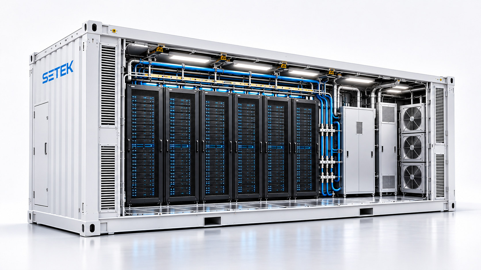
Illustrative product visualization. Layout and technical scope are project-specific.
PREFABRICATED · TRANSPORTABLE · EXPANDABLE
Modular data centers shift enclosure integration and agreed functional checks into the factory. Site work can proceed in parallel, while the package interfaces are coordinated in advance. This does not remove the need for site utilities, permits or commissioning.
Structural load paths, lifting points, corrosion protection, insulation, weather sealing and service doors must be designed for sensitive IT and mechanical equipment.
Ambient design temperatures, dust, moisture, condensation risk and ventilation strategy influence the enclosure, cooling equipment and ongoing operations.
Rack removal routes, access clearances, cable/piping penetrations, fire-safety interfaces and monitoring are planned before the design is frozen.
FACTORY TO FIELD
The project is divided into clear deliverables, without treating delivery time or cost savings as universal guarantees.
Schematic animated sequence — actual stages and FAT/SAT test scope are determined per project.
SETEK / INTERACTIVE ENGINEERING WORKSHEET
Develop an early-stage infrastructure envelope from rack density, PUE and cooling assumptions. Change the inputs to calculate electrical demand, UPS autonomy, heat removal, estimated fluid flow and energy costs in real time.
Nameplate, before margin
IT design capacity × modular PUE
IT heat plus capacity margin
Modular PUE, current IT demand
| Engineering parameter | Estimated result | Design interpretation |
|---|---|---|
| Installed rack IT power | — | Racks × rack kW (kW) |
| Operating IT power | — | Installed IT × average load factor (kW) |
| Protected IT design power | — | Installed IT + design reserve (kW) |
| Modular facility design power | — | IT design × modular scenario PUE (kW) |
| Utility service apparent power | — | Facility kW / power factor (kVA) |
| Indicative 3-phase line current | — | At entered line-to-line voltage and power factor (A) |
| UPS output power target | — | Critical IT design output (kW) |
| UPS nameplate apparent power | — | IT output / assumed load PF (kVA) |
| Indicative battery energy | — | UPS autonomy adjusted by usable battery factor (kWh) |
| Engineering parameter | Estimated result | Design interpretation |
|---|---|---|
| Total IT heat – design envelope | — | IT power × (1 + capacity margin) (kWth) |
| Liquid-side heat removal | — | Design IT heat × liquid capture (kWth) |
| Residual air heat removal | — | Design IT heat − liquid-side heat (kWth) |
| Total cooling in refrigeration tons | — | 1 RT ≈ 3.517 kW of heat removal |
| Facility-water flow estimate | — | Approximate water L/min at entered ΔT |
| Residual air volume estimate | — | Approximate m³/h at entered air ΔT |
| Liquid cooling units · N | — | Ceiling(liquid kW / unit nominal kW) |
| Liquid cooling units · N+1 concept | — | N plus one comparable standby unit |
| Scenario metric | Modular container | Building-type |
|---|---|---|
| Scenario PUE | — | — |
| Annual facility energy | — | — |
| Annual electricity cost | — | — |
| Editable facility CAPEX | — | — |
| Selected-horizon CAPEX + power | — | — |
Peak IT = rack count × kW/rack. Operating IT = peak IT × utilization. Design thermal load = peak IT × (1 + margin). Facility electric power = design IT × entered PUE; the operating-cost estimate uses operating IT × PUE × hours × tariff. Water flow assumes pure water, density ≈ 1 kg/L and specific heat ≈ 4.186 kJ/kg·K. Airflow assumes ≈ 1.2 kJ/m³·K. Liquid and air heat loads do not add compressor or pump electric losses separately.
Not a quotation or engineering approval: PUE, annual load factor, CAPEX and unit capacities are user-adjusted assumptions. Actual electrical feeder sizing, UPS battery selection, CDU hydraulic design, cooling performance, heat rejection, generator sizing, derating and N+1 availability need OEM data and site engineering. Results exclude power harmonics, startup current, battery discharge curves, liquid mixtures, maintenance, financing, taxation and IT hardware costs.
EVALUATE BEFORE ORDERING
Rack count, power density, server platform and future growth.
Incoming service, UPS autonomy, branch protection and redundancy.
Air or liquid cooling, heat rejection and seasonal climate.
Foundation, lifting route, utilities, setback and permit requirements.
Fire protection, access controls, environmental alarms and CCTV options.
Shipping limits, rigging loads, handling constraints and interfaces.
Monitoring, servicing, spare parts, modular growth or relocation.
THE SETEK PLATFORM
Standardized project gates support Model 20 and Model 40 concepts. Computing modules may be coordinated with separate power and cooling equipment when density, resilience or maintainability requires it.
Explore high-density AI modules ›THE ENCLOSURE IS PART OF THE SYSTEM
An industrial data center enclosure and a basic converted container may look similar from the outside. Their structural, thermal and environmental design criteria can be very different. Compare these manufacturer-supplied reference construction approaches.
| Design category | Engineered data center container | Low-cost converted container | Why it matters |
|---|---|---|---|
| Steel thickness | Example frame: 3.2–6.0 mm high-strength steel; panels: 1.6–2.3 mm | Example steel: 0.8–1.2 mm | Structural rigidity, equipment protection and impact resistance |
| Frame structure | Designed steel frame with H-beams or high-rigidity square sections | Simplified light-gauge frame arrangement | Must accommodate UPS, server rack, cooling and lifting loads |
| Floor & lifting | Partner reference cites industrial load arrangements exceeding 30 tonnes, subject to engineered design | May use a floor intended for less demanding loads | Crane lifting, concentrated equipment loads and frame integrity need verification |
| Welding quality | Designed full-penetration and controlled CO₂ / TIG weld processes where required | Partial welds or sealant-heavy finishing may be used | Leak resistance, impact performance and structural continuity |
| Thermal insulation | Example 50–150 mm polyurethane or mineral wool systems | Example 20–60 mm basic insulation | Cooling demand, condensation and interior environmental stability |
| Airtightness | Engineered sealing details and verified environmental openings | Infiltration and condensation control may be undefined | Humidity control, air leakage and equipment protection |
| Service life | Partner cites a 20+ year design-life concept with suitable maintenance | Partner example suggests shorter replacement cycles | Actual life depends on materials, corrosion exposure, quality and servicing |
| Design purpose | Purpose-engineered transportable IT infrastructure | General storage or temporary enclosure converted for equipment | IT protection requires coordinated structural, power and cooling engineering |
Manufacturer reference, not a universal rating: Material thicknesses, weight capacity, life expectancy and construction details are examples from DOBE Computing's published comparison. SETEK does not claim that all engineered or low-cost containers share these specifications. Obtain approved drawings, structural calculations, certificates and quality records for each quotation.
How SETEK evaluates engineering qualityONE MODULAR PLATFORM · THREE APPLICATION FAMILIES
Our containerized engineering approach is configured for general IT, high-density AI and specialized quantum technology—not one fixed product disguised as three.
Reliable modular infrastructure for mixed IT, edge deployments, communications and enterprise services.
Explore general & edge systems ↗ 02 / HIGH-DENSITY AIGPU-focused rack power, high-density direct liquid cooling, CDU integration and coordinated modular capacity.
Explore AI PMDC architecture ↗ 03 / SPECIALIZED QUANTUMOEM-led cryogenic support, electromagnetic and vibration review, precision controls and environmental systems.
Explore quantum requirements ↗YOUR REQUIREMENTS, OUR STARTING POINT
Share your intended workload, capacity, site conditions and resilience requirements. SETEK will coordinate the next engineering steps and scope.
Send a project enquiry ↗